Sketching Part 1
The primary way of generating geometry in OnShape is through Sketches. Sketches must be on a plane and are the starting point for extrusions. OhShape gives us 4 parts of default geometry:
- An origin point
- An XY plane
- An XZ plane
- A YZ plane
We are going to start our sketch on the YZ plane labelled 'top'.
Creating our first sketch
tip
Any time I do something and you cannot find the button to do it, there is a grey box on the right side of the toolbar that you can use to search tools. Use that instead of wasting too much time looking for a button.
In the top left of the page, you will see a button with a pencil icon and the text "Sketch":
Click the button. It will pop up a dialogue, with a title of "Sketch 1" and the input box "Sketch plane" selected (you can tell it is selected by the blue background). It is looking for you to select a plane to start the sketch on. As we said a few lines before, we are going to start our sketch on the YZ plane, so click the plane labeled "top" in the model view in the middle of your screen. Once the toolbar changes, do not click the green check box. That is like a 'save and close' button.
Once we have our sketch created, let's change our viewpoint to normal to the sketch plane. This makes it so we are looking directly at the sketch without any rotations or translations. To do this, we will click the 3d manipulator in the top right of the screen (a cube with 'top', 'front', and 'right' faces labeled). Right-click on this cube, then select the last option in the dialogue box "View normal to sketch plane".
Adding our first geometry
We are going to start by replicating some of GoBilda's pattern, so using the technical drawing, we will sketch out some basic geometry to use to attach our part. 4 screw holes should suffice (I have marked the 4 holes we are going to use in the following drawing in red).
In this case, the bottom drawing's data is more helpful, so it will be the base of our work.
Holes of interest marked
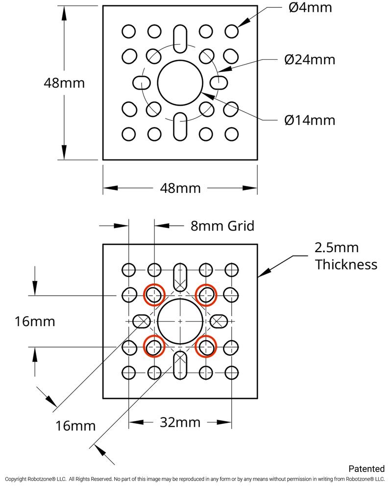
We know thanks to the drawing that the 4 holes we are interested are arranged on the corners of a square with 16mm long sides.
Remember from Geometry class how we had to do constructions? We have to use them all the time in cad, where we have to add extra geometry that we will not end up using, but we need it to properly lay out the other parts of the sketch.
We want to have our object centered at the origin point, so we will use that as the base of the square we are about to draw. Now, in the toolbar, you will see a rectangle tool (6th from the left). We aren't going to use the Corner Rectangle tool, but we are going to use the center point rectangle tool. To access it, we need to click the down arrow next to the rectangle tool, then select the center point rectangle tool. In the future, we can just use the r key to use this tool. Next, select the origin as the center point, then just draw out a rectangle. Don't worry about dimensions yet, we will tacke that in a second.
Once your rectangle is drawn, press escape once to exit the rectangle tool.
Dimensioning your geometry
Now we have to make this slightly oblong shape into a square. To do this, we will use the dimensioning tool and set each edge's length to 16mm. To access the dimension tool, press the d key on your keyboard.
tip
The dimension tool is the tool that you will use the most. It will make your life much easier if you get used to using the keyboard shortcut.
Select 2 sides of the rectangle, and set their dimensions to 16mm. OnShape will keep the shape a rectangle, so there is no point in dimensioning parallel lines.
Notice how OnShape automatically converts units if I just type their abbreviation into the dimension tool's input box.
You can change the scale of the drawing by scrolling as well.
Generating Constructions
Once you have your basic shape, it is time to turn your rectangle into a construction so we can use it to generate further geometry without having the smape affect the rest of your part.
Select each side of the rectangle and click q on your keyboard or the construction button as demonstrated in the video.
Building the shapes
You can use the circle tool to make circles to use for the holes. You can generate a center-point circle with the keybind c or the circle button just to the right of the rectangle. Now, draw a circle with the center over each corner of the square.
Dimensioning and equalizing the circles
Remember how we generate dimensions. Now we want to set up the diameter of the circles to be 4mm (refer to the top sketch on GoBilda's technical drawing, where they have annotated one of the screw holes to be 4mm) (the symbol for diameter is ⌀).
Set the diameter of one of the circles to be 4mm, then we will use the equality tool to make the diameters of the others always match the first.
We will set the diameter manually, then activate the equality tool, and select one of the undimensioned circles, then select the manually dimensioned circle (in that order). Repeat this for each remaining undimensioned circle.
Finishing the sketch
Now that you have 4 circles that are the right size and in the right locations, we are ready to finish the sketch! In the little dialogue box that popped up when you created the sketch, click the green check box.
Going back to our 3d view
Under the 3d manipulator, there is a small cube with a dropdown next to it. Click the dropdown, and select "Isometric". This will bring you back into the 3d view, recentering everything. The keyboard shortcut for this is shift + 7 (the 7 on the top of your keyboard, not in a numpad)